Xilinx provides a limited feature-set version of the MicroBlaze Soft Processor in the ISE WebPACK. The MicroBlaze allows for much higher level development tasks to be completed with ease. In the following I will show you how to setup a basic MicroBlaze project.
Begin by opening the ISE Project Navigator and creating a new project, ensuring you choose the correct settings for your specific device. VHDL or Verilog does not make a difference so feel free to pick what you are comfortable with. Right click on your device in the project hierarchy and click ‘New Source…’. Select ‘IP (CORE Generator & Architecture Wizard) as the type, and give it a file name.
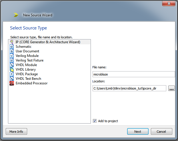
Select ‘MicroBlaze MCS’ from the Embedded Processing -> Processor subfolder and click next and finally finish. After a few moments the MicroBlaze generator will have appeared. It is within this window that we can choose all features we want to enable for our processor. It is important to ensure that you only enable features you need as each option will take up precious space on your design. It is also important that you remember the ‘Instance Hierarchical Design Name’ as we will need it later (in the picture below it is mcs_0). Go ahead and set the Input Clock Frequency to match that of your board, increase the Memory Size to 16KB and Enable Debug Support if you are so inclined.

For this example we will create a processor that will increment a byte by 1 every second, and output the value via UART and onto a set of LED’s. To do so we must go to the UART tab and click ‘Enable Receiver’, ‘Enable Transmitter’ and set the Baud Rate to whatever value you would like.

Next click the FIT (Fixed Interval Timer) tab, and click ‘Use Timer’ for FIT 1. Since we will be using this timer to create a millisecond delay feature, you’ll want to divide your clock by 1,000 to get the appropriate value. In my case my NEXYS 4 has a 100 MHz clock signal, so I would divide 100,000,000/1,000 = 100,000 to get my desired value. We’re also going to need the interrupt, so clic ‘Generate Interrupt’.
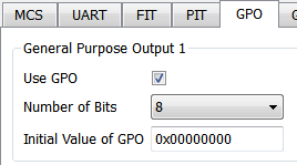
Finally click the GPO (General Purpose Output) tab, click ‘Use GPO’ for GPO 1, and set the number of bits to 8 (thus creating a 8 bit wide output port).
Click generate and ISE will begin to generate your processor. This process will take a few minutes so give it time to complete.

We now need to create a top file to instantiate our processor. Right click again on the project hierarchy and click ‘New Source…’ click either ‘Verilog Module’ or ‘VHDL Module’ and give it a name such as ‘microblaze_top’. ISE creates a HDL instantiation template we can insert into our top file, saving us a good amount of work. Click on the MicroBlaze xco file in the project hierarchy, and then in the window below expand ‘CORE Generator’ and double click ‘View HDL Instantiation Template’. This will open a window which will contain code similar to the lines below:
1 | //----------- Begin Cut here for INSTANTIATION Template ---// INST_TAG |
Copy this code and insert it into your top file. You can omit assigning signals to the FIT1 Interrupt and Toggle, as well as INTC_IRQ in this example since we will not be using them outside of the processor. Be sure to change ‘your_instance_name’ to the value you wrote down when generating the core (mcs_0 in this example). Your complete code should look similar to the following:
1 | module microblaze_top( |
At this point you’re going to want to generate a constraints file to map your I/O to sites available on your chip. We the need to execute a tcl script to setup the MicroBlaze so it is properly included in our synthesis. If you do not have the tcl console already open, click View -> Panels -> Tcl Console. Then type the following into the console:
1 | source ipcore_dir/microblaze_mcs_setup.tcl |
You should get output similar to the following:
1 | microblaze_mcs_setup: Found 1 MicroBlaze MCS core. microblaze_mcs_setup: Added "-bm" option for "microblaze.bmm" to ngdbuild command line options. microblaze_mcs_setup: Done. |
You’ll now want to implement the design by clicking the top file in the project hierarchy and in the list below right clicking ‘Implement Design’ and finally clicking run.
After your design is sucessfully implemented, it’s time to begin coding our processor. Open the Xilinx Software Development Kit application. When prompted for a workspace create a new folder called ‘workspace’ inside the folder of your ISE project and choose it. Close the welcome tab in the SDK window if it opens and you will now be sitting at the project interface. Click File -> New -> Application Project. Give the project a name, such as ‘microblaze_app’. Under Target Hardware, click the Hardware Platform drop-down and click ‘Create New’.

When the New Hardware Project window opens, click ‘Browse’ under Target Hardware Specification and browse inside the ipcore_dir of your project. Inside you will see a file named similar to ‘microblaze_sdk.xml’, select this file and click ok. Click finish to return to the New Project window. Ensure that our new hardware platform has been selected, the OS Platform is ‘standalone’, the Language is ‘C’ and ‘Create New’ is selected for Board Support Package. If all these are correct click next. Select ‘Hello World’ from available templates and click Finish.
The project will compile and you will have three new folders in the Project Explorer. Double click on the folder with the name you gave the project, such as ‘microblaze_app’, expand the src folder and double click ‘helloworld.c’. Here you will see the code that was generated. Modify the code so that it is similar to the code below:
1 | #include <stdio.h> |
Save the file and if the code does not auto compile, click Project -> Build All from the top menu. There is one last command we need to run in the tcl console to include our elf file we just created in our bit file. Go back to ISE and run the following command in the Tcl Console tab (change the values to the appropriate names if needed):
1 | microblaze_mcs_data2mem workspace/microblaze_app/Debug/microblaze_app.elf |
Which should generate the following output:
1 | microblaze_mcs_data2mem: Found 1 MicroBlaze MCS core. microblaze_mcs_data2mem: Using "microblaze_app.elf" for microblaze microblaze_mcs_data2mem: Added "-bd" options to bitgen command line. microblaze_mcs_data2mem: Running "data2mem" to create simulation files. microblaze_mcs_data2mem: Bitstream does not exist. Not running "data2mem" to update bitstream. microblaze_mcs_data2mem: Done. |
Right click ‘Generate Programming File’ in the Design window and click run to generate the bit file needed to program the board. Upon uploading to the board, you should see the LED’s incrementing every second to the corresponding value in binary. If you connect to the UART pins, you will also see the current value in decimal being printed every second.